11 Using radios on Powder
At a high level, there are two types of radios on Powder: Common of the Shelf (COTS) and Software Defined Radios (SDR). Using COTS radios is typically more straightforward as they are purpose-built for particular functionality. These include COTS User Equipment (UE) radios, such as 5G modem modules (attached to compute nodes) and handsets (i.e., a typical cellular phone); and COTS Open RAN Radio Units (O-RU) that implement the physical radio layer of a distributed system realizing a 5G gNodeB (using the 7.2x split in O-RAN terminology). On the other hand, SDRs are meant to be flexible; the key concept here is "software defined." An SDR isn’t specifically a 5G UE or O-RAN RU, nor is it an FM receiver, or a LoRa radio. Instead, it can take on any of these roles through software running on a companion compute node.
11.1 COTS Radios
Powder offers 5G NR COTS radios, both on the endpoint/handset/UE side, and on the Open RAN Radio Unit (O-RU) base station side. COTS radios normally fall into the scope of particular end-to-end use cases. Examples are covered in the the SRS/OCUDU 5G tutorial and in example profiles such as this one that sets up an end-to-end O-RAN compliant 5G system using OCUDU and a Benetel RAN 550 O-RU in the indoor OTA lab. The following profile assists with setting up a selectable set of Quectel RM520N-GL 5G COTS UE modems connected to companion NUC small form factor compute nodes. These UEs are intended to be used with a separate 5G core + base-station(s) (O-RAN CU/DU/RU, or monolithic gNodeB) experiment in the outdoor over-the-air environment.
11.1.1 COTS O-RU devices
Powder offers O-RU devices from Benetel and VVDN. In the indoor OTA lab, a Benetel RAN550 is available, and can work alongside the COTS UE and/or SDR-based UE devices in the lab. There are also Benetel RAN650 and VVDN MPRU O-RUs connected to COTS UEs and SDRs in the conducted RF matrix environment. These are connected as pairs (from the same vendor) in separate matrix "layers" with adjacent UE devices, where the path attenuation can be dynamically controlled. This setup allows for experimentation with single O-RUs, or two for handover, interference, etc.
In the outdoor environment, there are two Benetel RAN650 O-RU devices deployed at the MEB rooftop site, covering the MEB parking lot and some of the adjacent roads. Two VVDN MPRU O-RUs are currently deployed outdoors: One at the USTAR, and another at the Honors rooftop sites. These have overlapping coverage of the Wasatch Drive roadway that travels north-south and is located to the east of both of these buildings. These radios can be used individually, or paired for handover and other multi-radio scenarios. Both sets of O-RUs are in range of certain $(tb) fixed-location COTS UE and SDR radios, as well as shuttles that pass within their coverage area.
11.1.2 Management of O-RU devices on Powder
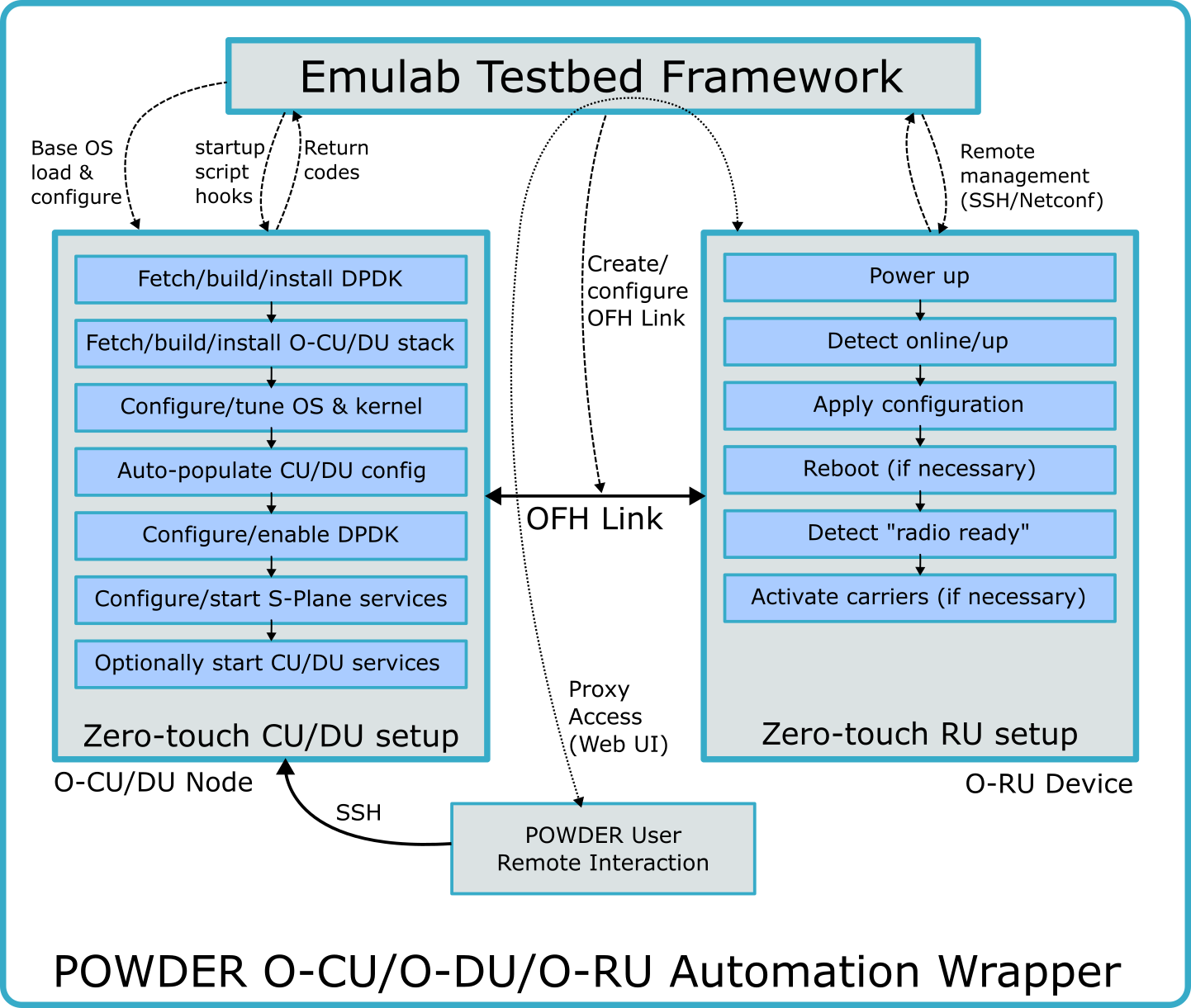
Powder’s COTS O-RU resources are not directcly accessible by users; instead, they are managed through proxy (wrapper) mechanisms that perform configuration tasks during experiment instantiation. This ensures that the radios are not misconfigured, and operate on frequencies declared by users and vetted by the $(tb) experimental framework via profile scripts. O-RU configuration parameters, such as operating frequency range (i.e., ARFCN and bandwidth), as well as other O-RAN parameters like OFH compression can be specified in profile scripts. The following code snippet shows how this is accomplished:
ru = request.COTSRU("myru") # Create object representing O-RU device ru.arfcn = 628000 # 3420 MHz center frequency ru.bandwidth = 40 # 40 MHz wide channel ru.ofh_compression_mode = "static" # Open fronthaul (OFH) compression mode ru_ofh_if = ru.addInterface("ofh-link") # Declare interface for OFH ru_ofh_if.PTP() # Request PTP clock delivery to this interface ru_ofh_if.SyncE() # Request SyncE clock delivery to this interface ru = request.COTSRU("myru") # Create object representing O-RU device ru.arfcn = 628000 # 3420 MHz center frequency ru.bandwidth = 40 # 40 MHz wide channel ru.ofh_compression_mode = "static" # Open fronthaul (OFH) compression mode ru_ofh_if = ru.addInterface("ofh-link") # Declare interface for OFH ru_ofh_if.PTP() # Request PTP clock delivery to this interface ru_ofh_if.SyncE() # Request SyncE clock delivery to this interface
Note: this example does not show the complete code required to set up an O-RU in an end-to-end 5G experiment. Please see the references provided above.
The table below lists the COTS RU parameters available at the time of writing. If something you are interested in changing does not appear here, please contact us to see if support has been (or could be) added.
Setting |
| Allowed Values |
| Description |
arfcn |
| 623868-646666 |
| 3GPP center frequency channel ID.(Reference) |
bandwidth |
| 10, 20, 40, 50, 60, 80, 90, 100 |
| 5G NR Channel bandwidth. Support may vary by radio. |
du_mac |
| Valid Ethernet address |
| Allows for specifying a virtual MAC address in your O-CU/DU configuration. |
ofh_compression_mode |
| static, dynamic |
| Allows for switching between 'static compressed', and 'dynamic compressed' OFH compression. |
Powder also provides automation to setup O-CU/DU nodes, adjusting their configuration based on the parameters specified in profile scripts. This automation also takes care of OFH network interface settings (DPDK, VLAN, and MAC address), which must be determined after experiment instantiation based on which radio devices are allocated, and what particular compute node they are paired with. The figure below provides an overview of the automation mechanisms that configures both O-RUs and O-CU/DU functions. Note that the O-CU/DU setup automation depends on using a profile that includes the requisite start-up scripts for the O-CU/DU node(s). Users should either use reference profiles provided by Powder when working with COTS O-RUs, or derive custom profiles based on these.
11.2 Software Defined Radios
Software Defined Radios (SDRs) allow for users to define how the radio will transmit and receive radio frequency (RF) signals, within their set of capabilities and limitations. In most cases, SDRs are tuned to a particular center frequency, operating over a given bandwidth (which is defined by sampling rate), and raw IQ samples are exchanged between the radio and its companion compute node. These samples are the digitized version of the real, analog signal that is transmitted out to, or received in from, RF ports on the SDR. Onboard the SDR are signal processing elements (implemented on an FPGA) that can operate on the IQ samples, and digital-to-analog (DAC) and analog-to-digital (ADC) converters to go between the digital representation and the analog signal. SDRs also have components on the analog front-end side that are typical of other radios, such as oscillators, amplifiers, and filters. This is an important point, as many SDRs at Powder have an additional, custom RF front-end designed and built by the Powder team that provides additional functionality (most importantly, additional link budget).
On the companion compute side, signal processing is accomplished in software with digital samples (the IQ samples mentioned previously). There are a large number of open source packages available for using SDRs with many different radio waveforms, modulation and coding schemes, and communication protocols. Several are ready to run out-of-the-box on Powder, usually offering some amount of configurability. These include tools like ‘uhd_siggen‘ and others that produce a simple constant or sine wave carrier signal (IQ samples), where the application requests that the SDR tune to a given center frequency, and then passes the IQ samples to be modulated at that frequency. Applications like ‘uhd_fft‘ and others display live signals by asking the radio to tune to a given center frequency and capture at a particular sampling rate. This provides a set of samples representing the signals in a range (channel) around the center frequency. We say that this channel has a "bandwidth", such as 5 MHz, that reprents the frequency range received by the radio and turned into samples by the ADC. The application takes these received samples, and plots them in some way in real-time. The plot might be a time-based view of the signal (amplitude over time), or a frequency analysis (FFT). More complex end-to-end software for SDRs include 5G gNodeB and UE functionality (OCUDU and OAI being two examples), LoRa tranmitter/receiver, an OFDM signal transmitter/receiver, etc. There are also workflow applications, such as GNU Radio that allow for defining SDR flow graphs based on drag-and-drop logical blocks that do things like decimate, filter, tune radio, etc. These provide a high-level abstraction of the radio. In order to have low-level access to the radio you would want to use vendor-specific libraries, such as UHD, or more general libraries such as SoapySDR. These provide programmatic interfaces for working directly with the SDRs.
11.2.1 SDRs on POWDER
All SDRs available on the Powder platform are models from the vendor NI (Ettus). The Powder team has deployed these to most environments: Rooftops, Fixed Endpoints, Mobile Endpoints, Dense Deployments, the indoor OTA lab, the controlled RF environment, and testbench pairs. Please review the hardware chapter to get more information on what radios are deployed where. Additionally, when logged into the Powder web UI, you can select "experiments -> Powder Radio Info" to see a table of radio information. The Powder map also shows the locations of sites, and clicking on them will bring up information about deployed radios as well as their current availability. $(tb) primarily makes use of NI X310 (w/ UBX160 daughterboards), B210, and N310 radios. There are links to the datasheets for these radios in the hardware chapter.
11.2.2 SDR Capabilities and Limitations
When using any SDR, it is important to understand its capabilities and limitations. The best place to start is with the datasheet for the specific radio. There are links to these datasheets in the hardware chapter. You will note that SDRs have attributes such as:
Number of RF ports and their type: TX, RX, or both (TX/RX)
Tunable frequency range, which indicates where in the RF spectrum you can tune the center frequncy to
Maximum sample rate, which indicates how large a channel you can sample around a given center frequency (per channel)
Gain (range), which affects the power of transmitted/received signals depending on how it’s set
Performance parameters, such as: ADC/DAC resolution, noise figure, maximum output power, phase noise, TX OIP3, etc.
An important thing to keep in mind is that Powder does not necessarily connect every RF port on an SDR. Carefully review the radio info page linked above for the details. If you end up selecting a port that is not connected, you will not recieve any meaningful signals, and your transmissions won’t go anywhere. For transmissions, most tools default to the "TX/RX" port on the first channel of the radio (i.e., "RF A" on B210 and X310 radios, and "RF 0" on N310 radios). For receiving, these tools default to the "RX2" port on the same first channel. Note that, nominally, "TX/RX" ports can be used for both transmission and reception, but not at the same time, and not with certain front-end setups on Powder. As an example, many of Powder’s rooftop radios only have the "TX/RX" port connected. These radios will require selecting the "TX/RX" port for receiving, or you will not receive the signal you are hoping for. Again, please be sure to review the radio info page for details.
11.2.3 SDR Calibration
SDRs from NI/Ettus - and likely from most other manufacturers - do not come calibrated to a reference power level. This means that at a given gain and frequency, the TX or RX signal power cannot be converted to dBm or Watts. The Powder team is working toward making calibration data available for each radio.
11.2.4 Working With Powder Custom RF Front-Ends
Several SDRs deployed at Powder have one of our custom RF front-ends attached. These front-ends provide additional transmit and receive gain, increasing maximum transmit power and reducing receive noise figure. They also provide the necessary switching for TDD operation. This does mean that you cannot transmit and receive at the same time from these devices. Transmit vs. receive mode is controlled by pin 4 of the SDR’s GPIO interface. Some frontends only have one channel while others have multiple channels; again check the radio information page for information on specific radios. Frontends are always connected to the first set of channels, i.e. a single channel frontend will always be connected to channel 0, a two-channel frontend to channels 0 and 1 and so forth. All channels switch between transmit and receive at the same time to prevent saturating the receivers with a transmit signal.
The frontends share a compatible GPIO interface. All frontends will be in receive mode when GPIO 4 is high and transmit mode when GPIO 4 is low. Some frontends will loop back a small amount of the transmit signal through a controlled path when GPIO 5 is high, and otherwise will have the RX TAP path turned off as normal when GPIO 5 is low. Asserting GPIO 4 and 5 high simultaneously is an invalid state and will turn both the transmit and receive sections off. All other pins are reserved and should be left low. The N310 defaults to output low on all pins. Therefore changing only the pins you need to use will leave all reserved pins in the proper state.

The transition between transmit and receive, in both directions, will complete in no more than 10 microseconds after the change in GPIO state. This time may be different between transmit to receive and receive to transmit, the guarantee is merely that it will complete in less than 10 us. You may choose to allow the radio to handle the switching for you using the example code shown below. In that case you need to only transmit or receive at any given point in time (start/stop the transmit/receive streams), and there will be up to a 10 us delay for the switch.
usrp->set_gpio_attr("FP0", "DDR", 0x10, 0x10); usrp->set_gpio_attr("FP0", "ATR_RX", 0x10, 0x10); usrp->set_gpio_attr("FP0", "CTRL", 0x10, 0x10); usrp->set_gpio_attr("FP0", "DDR", 0x10, 0x10); usrp->set_gpio_attr("FP0", "ATR_RX", 0x10, 0x10); usrp->set_gpio_attr("FP0", "CTRL", 0x10, 0x10);
If you need to control this more precisely, you should manually switch the GPIO yourself, as shown below. In order to specify the timing of the switching you will have needed to have previously setup the time of the radio using "set time next PPS" or similar.
// Initial setup usrp->set_gpio_attr("FP0", "DDR", 0x10, 0x10); usrp->set_gpio_attr("FP0", "CTRL", 0x00, 0x10); // Switch to TX uhd::time_spec_t time_spec = \ time_spec.from_ticks(time_to_switch_in_seconds); usrp->set_command_time(time_spec); // Set time to switch usrp->set_gpio_attr("FO0", "OUT", 0x0, 0x10); // Switch to RX uhd::time_spec_t time_spec = \ time_spec.from_ticks(time_to_switch_in_seconds); usrp->set_command_time(time_spec); // Set time to switch usrp->set_gpio_attr("FO0", "OUT", 0x10, 0x10); // Initial setup usrp->set_gpio_attr("FP0", "DDR", 0x10, 0x10); usrp->set_gpio_attr("FP0", "CTRL", 0x00, 0x10); // Switch to TX uhd::time_spec_t time_spec = \ time_spec.from_ticks(time_to_switch_in_seconds); usrp->set_command_time(time_spec); // Set time to switch usrp->set_gpio_attr("FO0", "OUT", 0x0, 0x10); // Switch to RX uhd::time_spec_t time_spec = \ time_spec.from_ticks(time_to_switch_in_seconds); usrp->set_command_time(time_spec); // Set time to switch usrp->set_gpio_attr("FO0", "OUT", 0x10, 0x10);
Pin |
| 0 |
| 1 |
| 2 |
| 3 |
| 4 |
| 5 |
Function |
| Reserved |
| Reserved |
| Reserved |
| Reserved |
| RX |
| RX_Tap |
Pin |
| 6 |
| 7 |
| 8 |
| 9 |
| 10 |
| 11 |
Function |
| Reserved |
| Reserved |
| Reserved |
| Reserved |
| Reserved |
| Reserved |
Pin 0 |
| Reserved, set to 0 |
Pin 1 |
| Reserved, set to 0 |
Pin 2 |
| Reserved, set to 0 |
Pin 3 |
| Reserved, set to 0 |
Pin 4 |
| RX, set to 1 to enter receive mode, 0 to enter transmit mode |
Pin 5 |
| RX_Tap, set to 1 to enter RX Tap mode when in transmit, |
| frontend will be in idle mode if RX Tap is asserted while in receive, | |
| 0 will disable the RX_Tap mode | |
Pin 6 |
| Reserved, set to 0 |
Pin 7 |
| Reserved, set to 0 |
Pin 8 |
| Reserved, set to 0 |
Pin 9 |
| Reserved, set to 0 |
Pin 10 |
| Reserved, set to 0 |
Pin 11 |
| Reserved, set to 0 |
11.2.5 Powder Custom RF Front-End Details
There are currently two custom RF frontends deployed on Powder, versions 1.0 and 1.1 of the CBRS/CBAND frontend. Increased transmit power, reduced receive noise figure, filtering and switching are the main features of these frontends. The frontends provide about 33 dBm out peak power out the transmit port. This is only peak power and will rapidly reduce as the power amplifier (PA) heats up. For signals with a peak-to-average power of about 10 dB (like the OFDM signals used in 4G and 5G) this is not a problem and this will be the peak power. CW signals will be reduced to about +25 - +27 dBm on the v1.0 frontend, and about +30 dBm on the v1.1 frontend.
On the receive side, the noise figure is about 6 dB. The frontends are both designed to work from 3.3 to 3.7 GHz, filters have been chosen to allow these frequencies though and reject frequencies outside this range. Transmit power is greater at the lower frequencies than the higher frequencies. This effect is more pronounced on the v1.0 frontends than the v1.1 frontends.
Finally the frontend includes the necessary switching hardware to go between transmit and receive at different points in time (TDD). As mentioned above, this is through pin 4 on the SDR’s GPIO. A high value tells the frontend to receive while a low value instructs the frontend to transmit. The switch will be completed within 10 microseconds of the edge on the GPIO line.
There are other features of the v1.1 frontend that will allow for measuring transmit and receive power in-situ. These will let users measure, in real time, the amount of power being transmitted out the transmit port as well as a special mode to tap off a controlled amount of power from this path into the receive path, allowing for calibration of the receiver power. We are working towards making these features available to users.
11.3 Radio Synchronization
For radios at Powder’s rooftop and dense deployment sites, synchronization signalling is provided for both SDRs and COTS O-RU devices. SDRs receive 1PPS and 10 MHz references via a centralized Safran (formerly Orolia, and before that, Seven Solutions) White Rabbit clock distribution system. This system provides sub-nanosecond accurate reference signals to the SDRs. The White Rabbit system is itself disciplined to GNSS/GPS through a FibroLAN uFalcon-MX/G primary reference time clock (PRTC). COTS O-RU radios at Powder receive S-Plane (PTP 1588-2008, ITU-T G.8275.1 + SyncE) signalling from the same FibroLAN GPS PRTC, distributed via Powder’s PTP+SyncE-complaint Ethernet fabric.
Important caveat with SDR timing: There are processing delays on NI SDRs vs. the 1PPS time base provided to them. This delay depends on the device model, firmware version, and the sample rate. Please ask for further details on the Powder Users Group. To make use of the externally provided clock signals, SDRs need to specifically request them. For existing scripts/programs, there are often command line switches for this. Otherwise, the source code that sets up the radio should request the external clock sources as discussed here.
Radios in Powder fixed endpoint and mobile endpoint deployments do not have any synchronization signals provided to them currently.