17 Hardware and Wireless Environments
As described in the Using Powder section, Powder provides a wide variety of hardware and configured environments for carrying out wireless research, including conducted and over-the-air (OTA) RF resources as well as backend computation resources. These resources are spread across the University of Utah campus as shown in the Powder Map. Conducted RF resources are largely in the MEB datacenter, OTA resources all across campus, "near edge" compute nodes in the MEB and Fort datacenters, and additional "cloud" compute nodes in the Downtown datacenter (not shown on the map).
Following is a brief description of these resources. For further information about the capabilities of, and restrictions on, the individual OTA components, refer to the Radio Information page at the Powder portal.
17.1 Conducted attenuator matrix resources
A custom-built JFW Industries 50PA-960 attenuator matrix allows for configurable conducted RF paths between a variety of connected components. While the actual RF paths are fixed, and must be manually configured by Powder personnel, users can adjust the attenuation values on those paths dynamically.
The current configuration of the RF paths can always be found on the Powder website. As of March 2025, the configuration was:
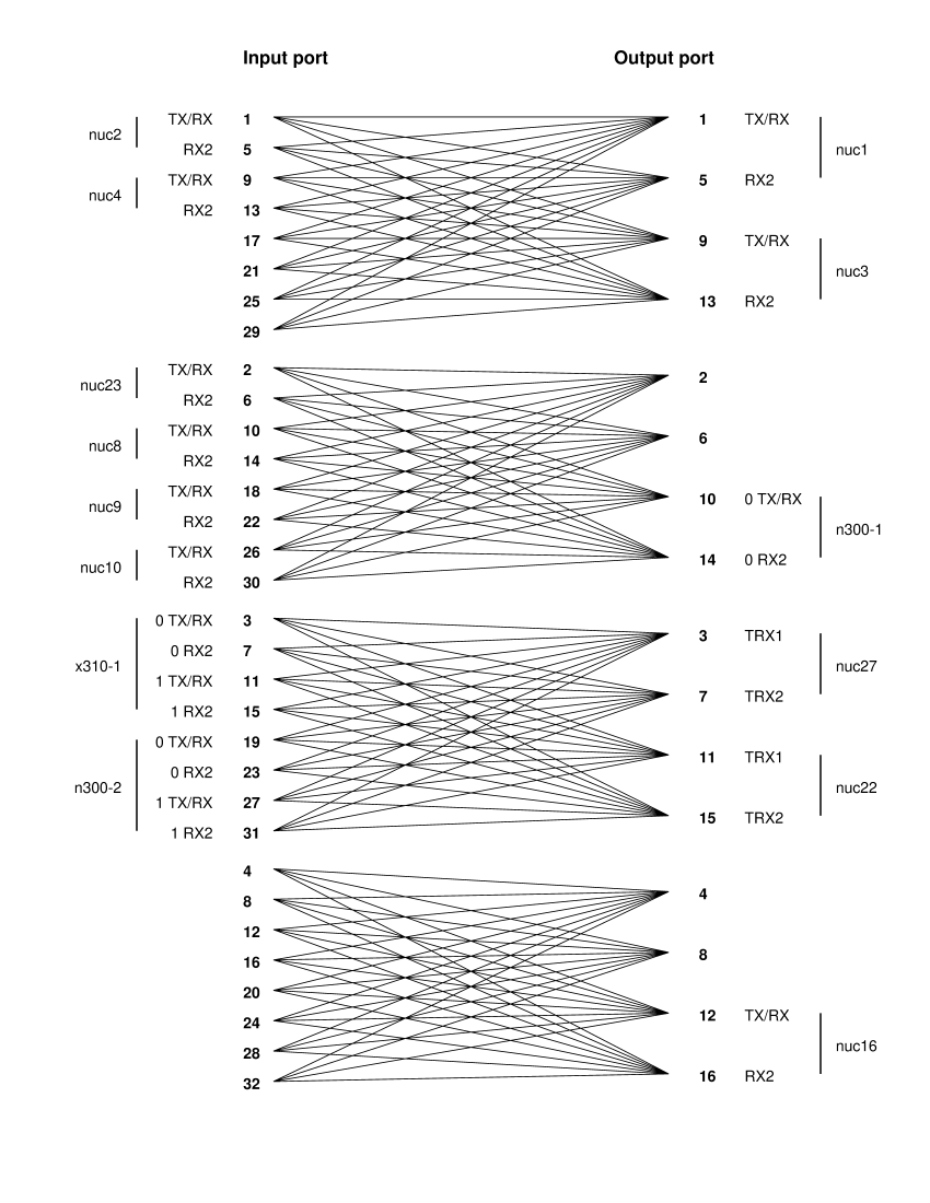
The connected components are:
Two NI N300 SDRs each with two 10Gb Ethernet connections to the Powder wired network. The Powder nodes names are n300-1 and n300-2.
One NI X310 SDR with two UBX160 daughter boards and two 10Gb Ethernet connections to the Powder wired network. The Powder node name is x310-1.
Eleven NI B210 SDRs each with a USB3 connection to an Intel NUC. The NUC provides basic compute capability and a 1Gb Ethernet connection to the Powder wired network. The majority of the NUCs (nuc1 to nuc4, nuc8 to nuc10, nuc16) are:
nuc5300
8 nodes (Maple Canyon, 2 cores)
CPU
Core i5-53000U processor (2 cores, 2.3Ghz)
RAM
16GB Memory (2 x 8GB DDR3 DIMMs)
Disks
128GB SATA 6Gbps SSD Drive
NIC
1GbE embedded NIC
The remaining NUCs (nuc22, nuc23, nuc27) are newer, with up to four cores and 32GB of RAM.
The N300 and X310 SDRs have their 1 PPS and 10 MHz clock inputs connected to an NI Octoclock-G module to provide a synchronized timing base. Currently the Octoclock is not synchronized to GPS. The B210 SDRs are not connected to the Octoclock.
17.2 Paired Radio workbench resources
The Paired Radio workbench consists of two sets of two NI X310 SDRs each, cross connected via SMA cables with a fixed 30 dB attenuation on each path. Connections are shown in this diagram:
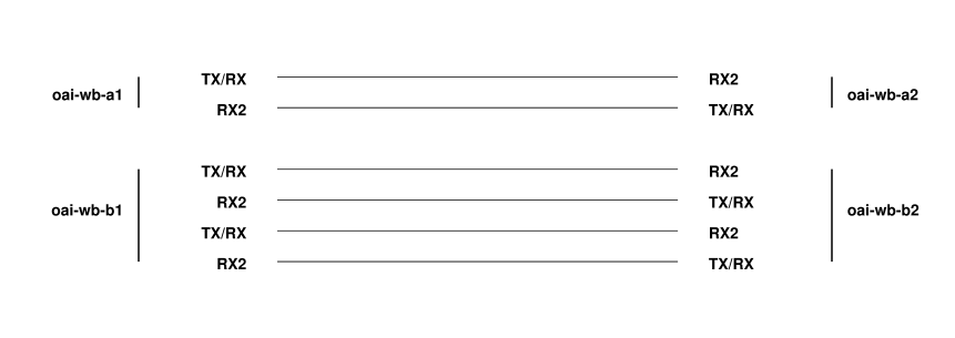
One pair, oai-wb-a1 and oai-wb-a2, has a single NI UBX160 daughter board along with a single 10Gb Ethernet port connected to the Powder wired network. The second pair, oai-wb-b1 and oai-wb-b2, has two NI UBX160 daughter boards and two 10Gb Ethernet ports connected to the Powder wired network.
All four X310 SDRs have their 1 PPS and 10 MHz clock inputs connected to an NI Octoclock-G module to provide a synchronized timing base. Currently the Octoclock is not synchronized to GPS.
17.3 Indoor OTA lab resources
The Indoor OTA environment consists of four NI B210 SDRs with antennas on one side of the lab, and four NI X310 SDRs with antennas on the opposite side of the lab:
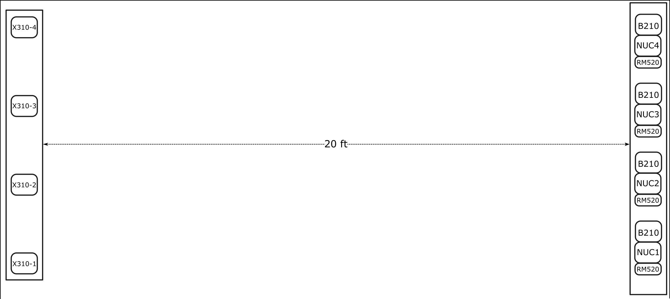
The four B210 devices are each connected to a four-port Taoglas MA963 antenna in a 2x2 MIMO configuration, meaning that the TX/RX and RX2 ports on both Channel A and Channel B are connected to an antenna element. The B210 port to antenna port connectivity is as follows: Channel A TX/RX to port 1; Channel A RX2 to port 2; Channel B RX2 to port 3; Channel B TX/RX to port 4.
The four B210 devices are accessed via USB from their associated Intel NUC nodes, ota-nuc1 to ota-nuc4. All NUCs are of the same type:
nuc8559 |
| 4 nodes (Coffee Lake, 4 cores) |
CPU |
| Core i7-8559U processor (4 cores, 2.7Ghz) |
RAM |
| 32GB Memory (2 x 16GB DDR4 DIMMs) |
Disks |
| 500GB NVMe SSD Drive |
NIC |
| 1GbE embedded NIC |
Also connected to each of the NUCs is a RM520N COTS UE connected to a four-port Taoglas MA963 antenna. Allocating the associated NUC will provide access to the COTS UE.
On the other side of the room, two of the X310 SDRs, ota-x310-2 and ota-x310-3, also have 2x2 MIMO capability via Taoglas GSA.8841 I-bar antennas connected to each of their Channel 0, and Channel 1 TX/RX and RX2 ports. The other two X310s, ota-x310-1 and ota-x310-4 have two of the I-bar antennas each, connected to the TX/RX and RX2 ports of channel 0 only.
All radios (X310s and B210s) have their 1 PPS and 10 MHz clock inputs connected to Octoclock-G modules to provide a synchronized timing base. The X310 devices connect to one Octoclock, and the B210 devices connect to another, with the two Octoclocks interconnected. Currently the Octoclocks are not synchronized to GPS.
17.4 Rooftop site resources
Powder currently has seven rooftop sites around the main University of Utah campus, as highlighted on this map:
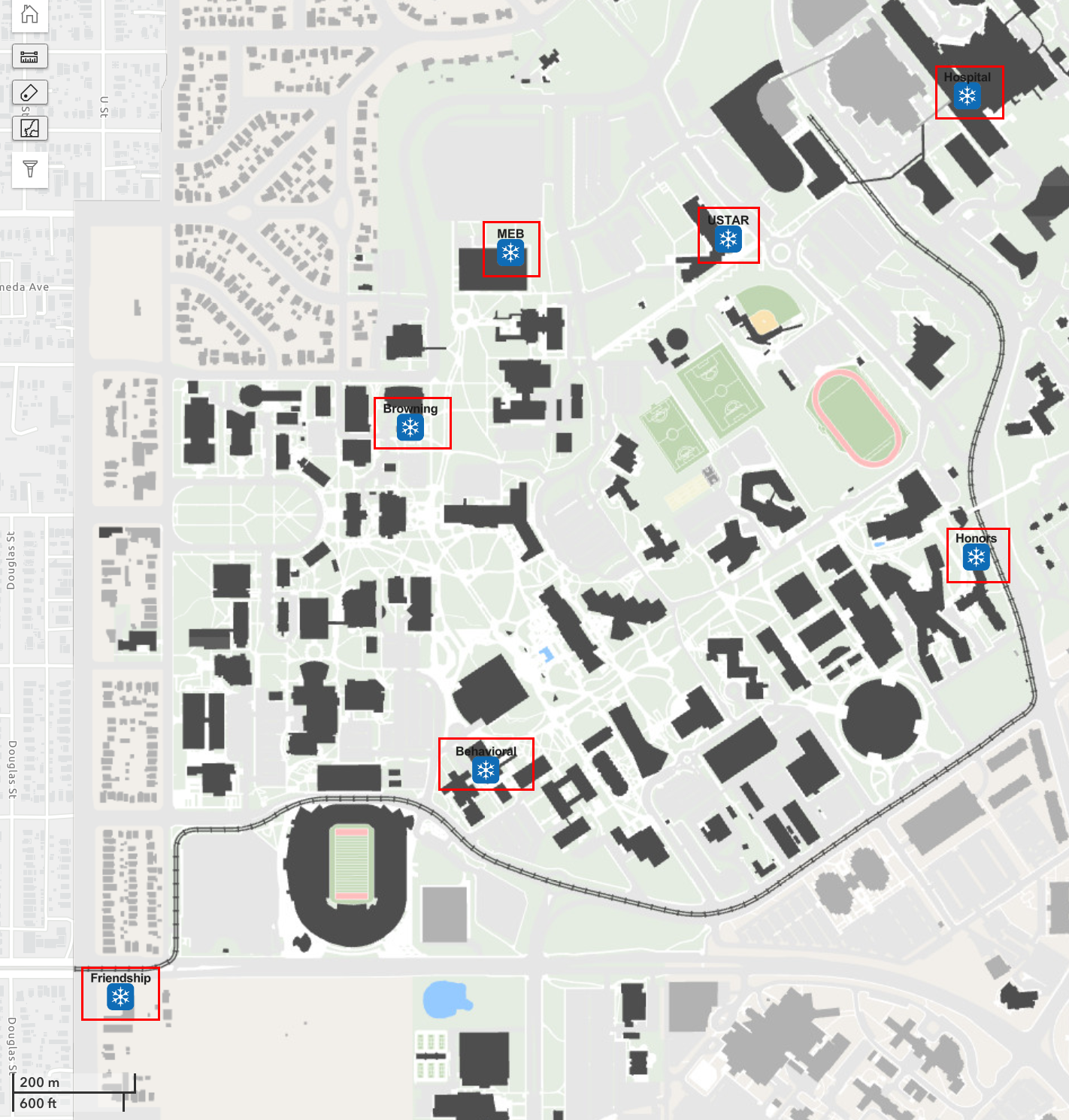
(For a better sense of scale and location relative to all resources, see the Powder Map.) The siteids (used for node naming) for each site are (clockwise from top right): Hospital (hospital), Honors (honors), Behavioral (bes), Friendship (fm), Browning (browning), MEB (meb), and USTAR (ustar).
Each Powder rooftop site includes a climate-controlled enclosure containing radio devices connected to Commscope and Keysight antennas. Each device has one or more dedicated 10G links to aggregation switches at the Fort Douglas datacenter. These network connections can be flexibly paired with compute at the aggregation point or slightly further upstream with Emulab/CloudLab resources.
One NI X310 SDR with a UBX160 daughter board connected to a Commscope VVSSP-360S-F multi-band antenna. The TX/RX port of the X310 is connected to one of the 3200-3800 MHz ports on the Commscope antenna. The radio can operate in TDD mode, transmit only, or receive only using that port. The X310 has two 10Gb Ethernet ports connected to the Powder wired network. These SDRs are available at all rooftops with the Powder node name: cbrssdr1-siteid, where siteid is one of: bes, browning, fm, honors, hospital, meb, or ustar.
One NI X310 SDR with a single UBX160 daughter board connected to a Keysight N6850A broadband omnidirectional antenna. The X310 RX2 port is connected to the wideband Keysight antenna and is receive-only. The X310 has a single 10Gb Ethernet port connected to the Powder wired network. These SDRs are only available at a subset of the rooftop sites with the Powder node names cellsdr1-siteid, where siteid is one of: hospital, bes, or browning. NOTE: The other rooftop sites do not have this connection due to isolation issues with nearby commercial cellular transmitters (too much power that would damage the receiver).
Skylark Wireless Massive MIMO Equipment. NOTE: Please refer to the Massive MIMO on POWDER documentation for complete and up-to-date information on using the massive MIMO equipment.
Briefly, Skylark equipment consists of chains of multiple radios connected through a central hub. This hub is 64x64 capable, and has 4 x 10 Gb Ethernet backhaul connectivity. Powder provides compute and RAM intensive Dell R840 nodes (see compute section below) for pairing with the massive MIMO equipment.
Massive MIMO deployments are available at the Honors, USTAR, and MEB sites (Powder names: mmimo1-honors, mmimo1-meb, and mmimo1-ustar).
A Safran (formerly Seven Solutions) WR-LEN endpoint. Part of a common White Rabbit time distribution network used to synchronize radios at all rooftop and dense sites.
An NI Octoclock-G module to provide a synchronized timing base to all SDRs. The Octoclock is synchronized with all other rooftop and dense and GPS via the White Rabbit network.
A low-powered Intel NUC for environmental, connectivity, and RF monitoring and management.
A Dell 1Gb network switch for connecting devices inside the enclosure.
An fs.com passive CWDM mux for multiplexing multiple 1Gb/10Gb connections over a single fiber-pair backhaul to the Fort datacenter.
A managed PDU to allow remote power control of devices inside the enclosure.
17.5 Dense-deployment site resources
Powder currently has five street-side and one rooftop site located in a dense configuration around one common shuttle route on the main University of Utah campus. The sites are highlighted in red and the shuttle route shown in green on this map:
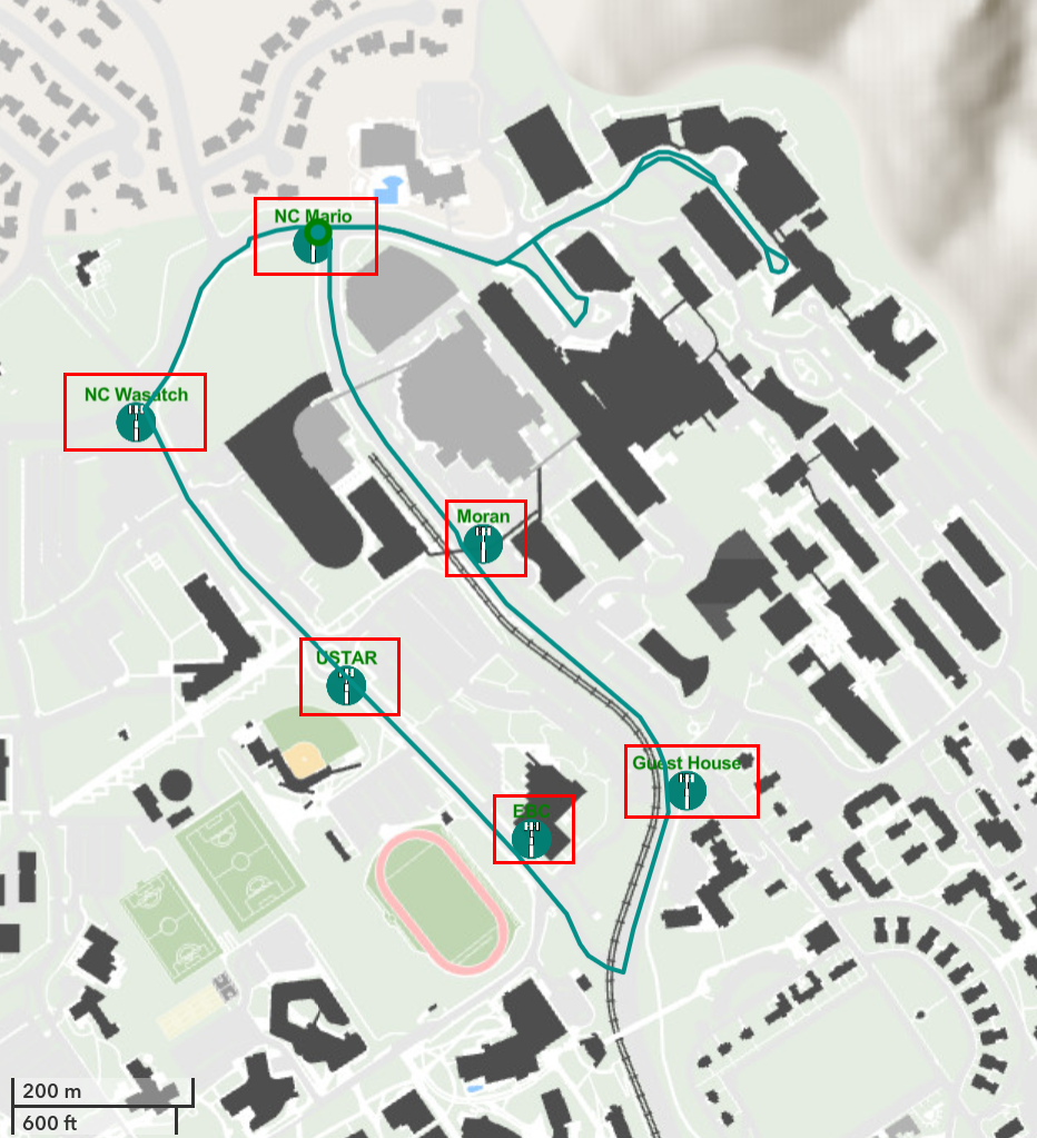
(For a better sense of scale and location relative to all resources, see the Powder Map.) The siteids) (used for node naming) for each site are (clockwise from upper left): NC Wasatch (wasatch), NC Mario (mario), Moran (moran), Guest House (guesthouse), EBC (ebc), and USTAR (ustar).
Powder dense deployment locations contain one or more radio devices connected to a Commscope antenna and a small compute node connected via fiber to the Fort Douglas aggregation point.
NI B210 SDR connected to a Commscope VVSSP-360S-F multi-band antenna. The Channel ’A’ TX/RX port is connected to a CBRS port of the antenna. The B210 is accessed via a USB3 connection to a Neousys Nuvo-7501 ruggedized compute node:
nuvo7501
1 nodes (Coffee Lake, 4 cores)
CPU
Intel Core i3-8100T (4 cores, 3.1GHz}
RAM
32GB wide-temperature range RAM
Disks
512GB wide-temperature range SATA SSD storage
NIC
1GbE embedded NIC
The compute node is connected via two 1Gbps connections to a local switch which in turn uplinks via 10Gb fiber to the Fort datacenter.
The Powder compute node name is cnode-siteid, where siteid is one of: ebc, guesthouse, mario, moran, ustar, or wasatch.
Benetel RU-650.
A Safran (formerly Seven Solutions) WR-LEN endpoint. Part of a common White Rabbit time distribution network used to synchronize radios at all rooftop and dense sites.
Locally designed/built RF frontend/switch.
A 1Gb/10Gb network switch for connecting devices inside the enclosure.
An fs.com passive CWDM mux for multiplexing multiple 1Gb/10Gb connections over a single fiber-pair backhaul to the Fort datacenter.
A managed PDU to allow remote power control of devices inside the enclosure.
17.6 Fixed-endpoint resources
Powder has ten "fixed endpoint" (FE) installations which are enclosures permanently affixed to the sides of buildings at roughly human height (5-6ft). The endpoints are highlighted in red on the following map:
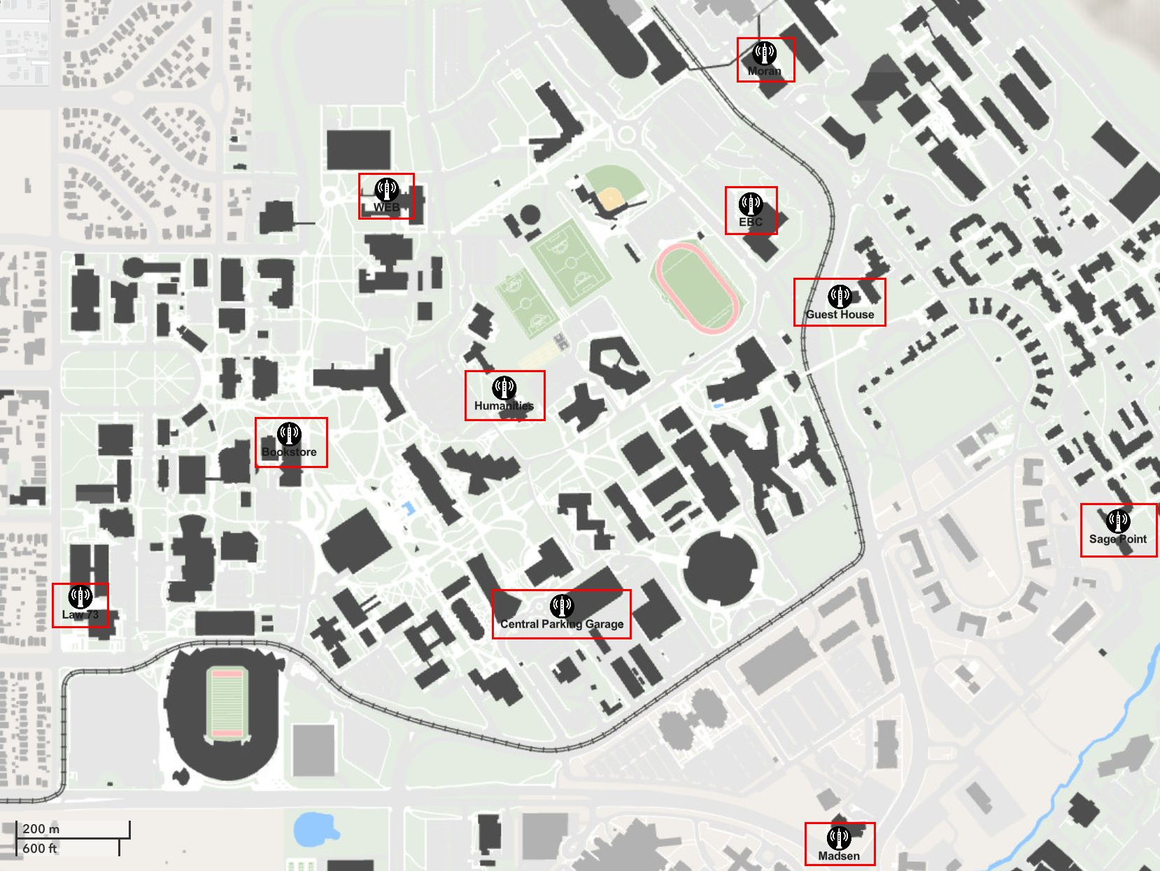
(For a better sense of scale and location relative to all resources, see the Powder Map.) The siteids) (used for node naming) for each FE are (clockwise from top right): Moran (moran), EBC (ebc), Guest House (guesthouse), Sage Point (sagepoint), Madsen (madsen), Central Parking Garage (cpg), Law 73 (law73), Bookstore (bookstore), Humanities (humanities), and WEB (web).
Each Powder FE enclosure contains an ensemble of radio equipment with complementary small form factor compute nodes. Unlike rooftop and dense sites, FEs do not have fiber backhaul connectivity. Instead they use commercial cellular and Campus WiFi to provide seamless access to resources.
One Quectel RM520N COTS UE connected to four Taoglas GSA.8841 I-bar antennas. The UE is USB3 connected to a NUC to provide basic compute capability and a 1Gb Ethernet connection to provide external access. This NUC is known as nuc1 and is the resource allocated to use the radio.
One receive-only NI B210 SDR connected to a Taoglas GSA.8841 I-bar antenna via the channel ’A’ RX2 port. The B210 is USB3 connected to the same NUC (nuc1) as the receive-only B210.
One transmit and receive NI B210 SDR connected to a Taoglas GSA.8841 I-bar antenna via the channel ’A’ TX/RX port. The B210 is USB3 connected to a NUC to provide basic compute capability and a 1Gb Ethernet connection to provide external access. This NUC is known as nuc2 and is the resource allocated to use the radio.
Both NUC compute nodes are:
nuc8559 |
| 4 nodes (Coffee Lake, 4 cores) |
CPU |
| Core i7-8559U processor (4 cores, 2.7Ghz) |
RAM |
| 32GB Memory (2 x 16GB DDR4 DIMMs) |
Disks |
| 250GB NVMe SSD Drive |
NIC |
| 1GbE embedded NIC |
17.7 Mobile-endpoint resources
Powder has twenty "mobile endpoint" (ME) installations which are enclosures mounted on a rear shelf inside of campus shuttle buses.
As with MEs, each Powder FE enclosure contains radio equipment and an associated small form factor compute nodes and they use commercial cellular and Campus WiFi to provide seamless access to resources. However unlike FEs, not all MEs are likely to be available at any time. Only shuttles that are running and on a route are available for allocation. For a map of the bus routes and their proximate Powder resources see the Powder Map.
One Quectel RM520N COTS UE connected to a four-port Taoglas MA963 antenna. The UE is USB3 connected to a Supermicro small form factor node to provide basic compute capability and a 1Gb Ethernet connection to provide external access. This node is known as ed1 and is the resource allocated to use the radio.
One NI B210 SDR connected to a Taoglas GSA.8841 I-bar antenna via the channel ’A’ TX/RX port. The B210 is likewise USB3 connected to the Supermicro node ed1.
The Supermicro Compute Node is:
e300-8d |
| 20 nodes (Broadwell, 4 cores) |
CPU |
| Intel Xeon processor D-1518 SoC (4-core, 2.2GHz) |
RAM |
| 64GB Memory (2 x 32GB Hynix 2667MHz DDR4 DIMMs) |
Disks |
| 480GB Intel SSDSCKKB480G8 SATA SSD Drive |
NIC |
| 2 x 10Gb Intel SoC Ethernet |
17.8 Near-edge computing resources
As previously documented, all rooftop and dense sites are connected via fiber to the Fort Douglas datacenter. The fibers are connected to a collection of CWDM muxes (one per site) which break out to 1Gb/10Gb connections to a set of three Dell S5248F-ON Ethernet switches. The three switches are interconnected via 2 x 100Gb links and all host 10Gb connections from the rooftop and dense sites. One switch also serves as the aggregation switch with 100Gb uplinks to the MEB and DDC datacenters that contain further Powder resources and uplinks to Emulab and CloudLab.
There are 37 servers dedicated to Powder use:
d740 |
| 16 nodes (Skylake, 24 cores) |
CPU |
| 2 x Xeon Gold 6126 processors (12 cores, 2.6Ghz) |
RAM |
| 96GB Memory (12 x 8GB RDIMMs, 2.67MT/s) |
Disks |
| 2 x 240GB SATA 6Gbps SSD Drives |
NIC |
| 10GbE Dual port embedded Intel X710 NIC (one port available for experiment use) |
NIC |
| 10GbE Dual port Intel X710 NIC (both ports available for experiment use) |
GPU |
| Two NVIDIA 12GB Tesla K80, PCIe |
NOTE: Only half of the d740 nodes have GPUs. Specify the "GPU" feature in your profile to ensure that you get a node with GPUs.
d840 |
| 3 nodes (Skylake, 64 cores) |
CPU |
| 4 x Xeon Gold 6130 processors (16 cores, 2.1Ghz) |
RAM |
| 768GB Memory (24 x 32GB RDIMMs, 2.67MT/s) |
Disks |
| 240GB SATA 6Gbps SSD Drive |
Disks |
| 4 x 1.6TB NVMe SSD Drive |
NIC |
| 10GbE Dual port embedded Intel X710 NIC |
NIC |
| 40GbE Dual port Intel XL710 NIC (both ports available for experiment use) |
GPU |
| NVIDIA 40GB A100, PCIe |
In early 2025, we added 18 new nodes along with the existing 19. All feature Intel E810 25GbE NICs and PTP capability and Intel ACC vRAN accelerators. Twelve are “general purpose” compute nodes, four have NVIDIA L40S GPUs, and two feature Nvidia Bluefield-3 DPUs and H100 NVL GPUs. The nodes are split across the Fort and MEB datacenters with not all nodes in their final destination or having their final experiment network connectivity. For the moment, all have at least two 25GbE or 100GbE connectivity.
d760p |
| 12 nodes (Emerald Rapids, 16 cores) |
CPU |
| Xeon Gold 6526Y processor (16 cores, 2.8Ghz) |
RAM |
| 128GB Memory (8 x 16GB RDIMMs, 5600MT/s) |
Disks |
| 480GB SATA 6Gbps SSD Drive |
Disks |
| 2 x 800GB NVME SSD Drives |
NIC |
| 25GbE Quad port Intel E810-XXVDA4 NIC (two ports available for experiment use) |
Accel |
| Intel vRAN Accelerator ACC100 |
d760-gpu |
| 4 nodes (Emerald Rapids, 64 cores) |
CPU |
| 2 x Xeon Gold 6548N (32 cores, 2.8Ghz) |
RAM |
| 256GB Memory (16 x 16GB RDIMMs, 5600MT/s) |
Disks |
| 2 x 16TB NVME SSD Drives |
NIC |
| 25GbE Quad port Intel E810-XXVDA4 NIC (two ports available for experiment use) |
NIC |
| 100GbE Dual port Mellanox ConnectX-6 DX NIC (both ports available for experiment use) |
GPU |
| NVIDIA 48GB L40S, PCIe |
Accel |
| Intel vRAN Accelerator ACC100 |
d760-hgpu |
| 2 nodes (Emerald Rapids, 64 cores) |
CPU |
| 2 x Xeon Gold 6548N (32 cores, 2.8Ghz) |
RAM |
| 512GB Memory (16 x 32GB RDIMMs, 5600MT/s) |
Disks |
| 2 x 16TB NVME SSD Drives |
NIC |
| Nvidia BlueField-3 Dual Port 100GbE (both ports available for experiment use) |
GPU |
| NVIDIA 94GB H100 NVL, PCIe |
Accel |
| Intel vRAN Accelerator ACC100 |
All nodes are connected to two networks:
A 10 Gbps Ethernet “control network”—
this network is used for remote access, experiment management, etc., and is connected to the public Internet. When you log in to nodes in your experiment using ssh, this is the network you are using. You should not use this network as part of the experiments you run in Powder. A 10/25/40/100 Gbps Ethernet “experimental network”. Each d740 node has three 10Gb interfaces, one connected to each of two Dell S5248F-ON datacenter switches. Each d840 node has two 40Gb interfaces, both connected to the switch which also hosts the corresponding Skylark mMIMO hub connections. Each d760p node has two 25Gb interfaces. Each d760-gpu node has two 100Gb interfaces. Each d760-hgpu node has two 100Gb interfaces.
17.9 Cloud computing resources
In addition, Powder can allocate bare-metal computing resources on any one of several federated clusters, including CloudLab and Emulab. The closest (latency-wise) and most plentiful cloud nodes are the Emulab d430 nodes:
d430 |
| 160 nodes (Haswell, 16 core, 3 disks) |
CPU |
| Two Intel E5-2630v3 8-Core CPUs at 2.4 GHz (Haswell) |
RAM |
| 64GB ECC Memory (8x 8 GB DDR4 2133MT/s) |
Disk |
| One 200 GB 6G SATA SSD |
Disk |
| Two 1 TB 7.2K RPM 6G SATA HDDs |
NIC |
| Two or four Intel I350 1GbE NICs |
NIC |
| Two or four Intel X710 10GbE NICs |
which have multiple 10Gb Ethernet interfaces and 80Gbs connectivity to the Powder switch fabric.